
Little trace now remains of the former Thames & Severn Canal pumping station at Thames Head, near Coates. The engine was removed in 1941 in the drive for scrap metal during the Second World War, and as late as 1974 the well, which supplied the water for the canal, was filled-in.
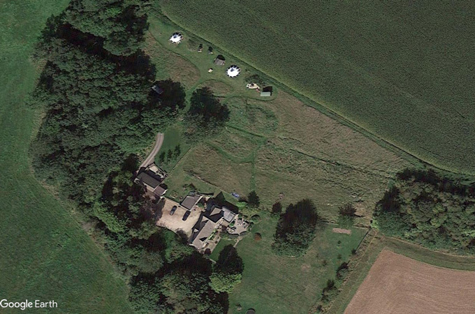
The site is now occupied by a private house, part of which is believed to have been converted from one of the original pumping station buildings in the 1970s.
The last time the pumping station was known to have operated was in 1912 which, perhaps oddly, was one year after the last boat was recorded as having passed through Sapperton Canal Tunnel.
The engine house contained a single Boulton & Watt Cornish-type pumping engine. This was supplied with steam from a coal-fired boiler in an adjacent Boiler House.
The pumping station first became operational in the summer of 1794, but the original engine was replaced by a newer and much more efficient engine in 1854.
Pumping Station Drawing
This graphic has been recreated using contemporary photographs.
History
Soon after the Thames & Severn canal opened in 1789, the canal company realised that the water supply to the summit was "wholly inadequate". This was mostly provided by a feeder from Jenour's (Barton) Mill in Cirencester using water from the River Churn, and a wind pump at Thames Head which drew water up from a well.
However, these did not provide a reliable enough source of water during periods of low rainfall.
Wind Pump - 1788
A six-bladed wind pump was installed in around 1788 near Thames Head bridge on the A433, Cirencester-to-Tetbury road.
This contained an 11-inch (28 cm) pump which supplied water from a 54ft (16.5 m) deep well into the summit pound. It is quoted as having a capacity of "several tons of water every minute".
However, this seems unlikely as it would equate to about 40,000 gallons (181,843 litres) per hour which far exceeds the capacity of modern wind pumps of a similar size.
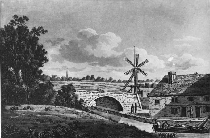
(Courtesy Gloucestershire Archives - Ref. GPS 609/8)
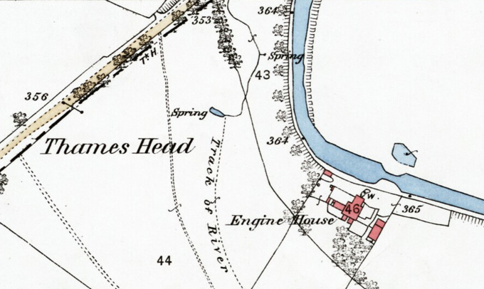
The wind pump was superseded by the pumping station which was located about 300 m or so to the east.
First Steam Engine - 1794
In 1791 the Thames & Severn Canal Navigation Company signed an indenture (agreement) with James Watt and Matthew Bouton to allow their patented 50-inch (127 cm) cylinder beam engine design to be used on the Thames & Severn Canal.
The agreement was for 25 years, with an annual fee payable of £120 (pounds).
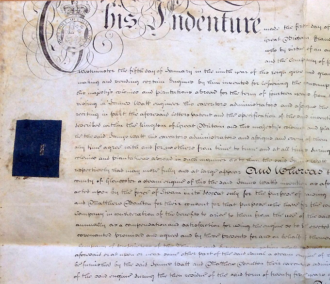
(Courtesy Gloucestershire Archives - Ref. TS208-1)
Boulton & Watt did not supply an engine though - just a set of engineering drawings, most of which survive in the Archives Division of Birmingham Central Library.
The principal engine parts and boiler were manufactured by John "Iron-Mad" Wilkinson. He was an industrialist who pioneered the use and manufacture of cast iron and cast-iron goods and the inventor of a precision boring machine used to bore cast iron cylinders used on steam engines.
The engine was assembled at Thames Head by a team led by Isaac Perrins, a well-known prize-fighter of the time.
By September 1792, the engine & boiler house and other ancillary buildings had been built and the engine installed. On the 22nd of September, the engine was fired-up for the first time.
It took a further year or more to finish excavating the new well and some of the connected underground galleries. So it wasn't until the following summer, on 14 June 1794, that the pumping station was finally operational, nearly three-and-a-half years after the Boulton & Watt agreement was signed.
Engine Refurbishment - 1833
After about 40 years of operation the engine underwent a significant overhaul which included installing two new 'waggon' boilers, manufactured by the Cinderford Iron Company.
In addition, the chimney stack was heightened, and other improvements were made to the engine itself.
Replacement Engine - 1854
By the 1840s it was clear that advances in steam engine 'technology' had left the original engine looking rather inefficient by the standards of the day. It wasn't until October 1853, however, that the decision was taken by the canal company to seek a replacement.
A virtually brand new engine was acquired from an auction of equipment from Tremar Mine near Liskeard in Cornwall. This former copper mine had only been in existence for about 2 years before it was deemed unprofitable and closed. The engine had been built in 1852 by Thomas & Co. at the Charlestown Foundry in Cornwall.
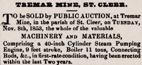
Over a period of 11 weeks in 1854 the engine was installed at Thames Head, and was operational on April 28. The original engine was sold for scrap.
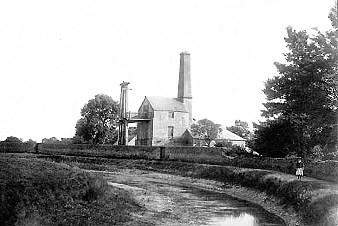
[Courtesy Oxfordshire County Council (H. Taunt)]
The engine was only operated in the dry season, which would typically be from June until the end of October. By the end of this period the springs and river that supplied the canal would usually be flowing reliably again.
The engine could supply up to 3 million gallons of water a day when operated continuously for 24 hours. Each time a boat passed through the 8-mile long summit pound, two lock-fulls of water would need to be replaced. However most water was lost through leakage.
Weekly depth measurements were taken at Siddington stop plank sill, along with a record of boat traffic, and the average number of hours per day water was taken from the Jenour's Mill feeder. A number of these forms survive in the Gloucestershire Archives.
New Boiler - 1888
In October 1887 an inspection was made of the Thames Head boiler following a boiler explosion at Brierley Hill in the West Midlands, which claimed the lives of 7 men.
The result was that the Thames Head boiler was declared 'not up to modern standards'. The cost of repairing the boiler was deemed uneconomic, so a replacement was sought.
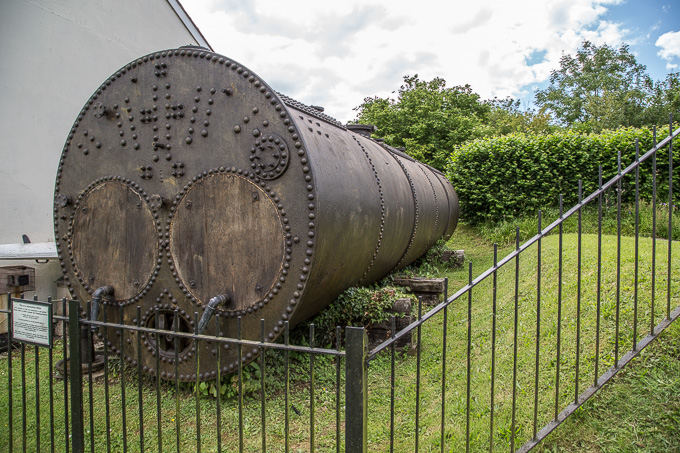
A new 'Lancashire' type boiler was ordered from the Company of Galloways in Manchester. The boiler was about 30ft long (9.1 m) and 6ft in diameter (1.8 m), and weighed about 11 tons with fittings attached.
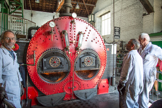
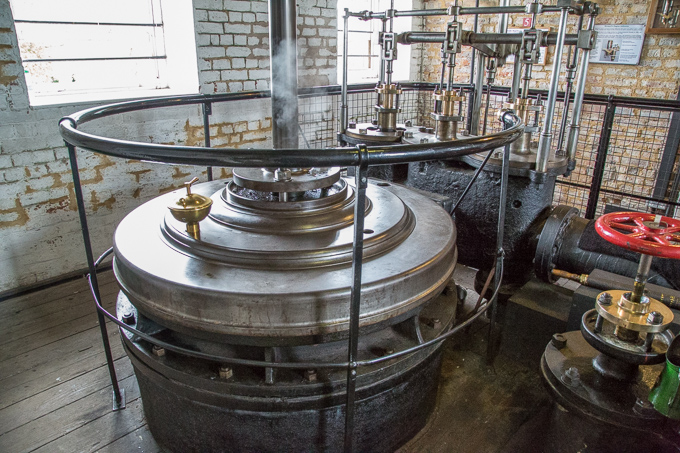
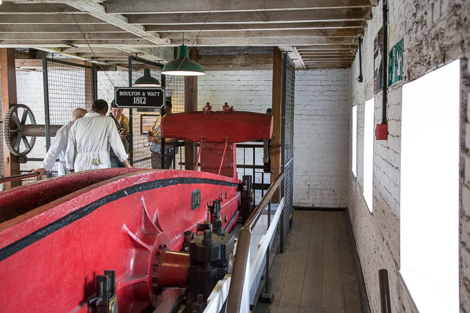
This article uses a number of photos taken at the Kennett and Avon Canal's pumping station at Crofton, Wiltshire, to better illustrate what the Thames & Severn pumping station might have looked like when it existed.
(on the Kennett & Avon Canal (K&A))
In March 1888 this was delivered by the Great Western Railway Company and off-loaded onto a company barge at Coates, where the railway crosses the canal. From here it made the 1.5 mile (2.3km) journey east along the canal to the Pumping Station. The new boiler was installed and operational in April 1888.
Operation of the Engine
Describing in detail how a Cornish Beam engine works is beyond the scope of this article (other sources of information are listed at the bottom of the page). But, put simply, 'high pressure' steam (about 20 psi in the 1854 engine) was produced by heating water in a boiler by burning coal.
Steam from the boiler was directed into a large cylinder inside the engine house through a control valve. A rod from a piston within the cylinder was connected to the right-hand end of the engine beam (shown in red in the Pumping Station graphic above).
For a single-acting cylinder, the piston inside the cylinder moves down in response to steam that had been drawn into the cylinder during the 'up' stroke being condensed (changed back to water) by injecting cold water into the cylinder. This creates a partial vacuum that effectively 'sucks' the piston down.
For the return (up) stroke, the piston is raised to the top of the cylinder by the weight of the pump rod, attached to the other (outdoor) end of the beam, pulling the beam down which happens when the partial vacuum in the cylinder is released.
The long pump rod was connected a 'bucket pump' down in the well. The rocking action of the engine beam operated the pump which lifted water up from the well. From here the water would run along a short channel and into the canal.
There was a stop plank point at the Pumping Station and water from the pump could be directed to either side, if the stop planks were fitted.
Coal Supply
Coal for the Thames Head boilers was supplied by boat, probably from the Forest of Dean, and there was a coal yard next to the pumping station.
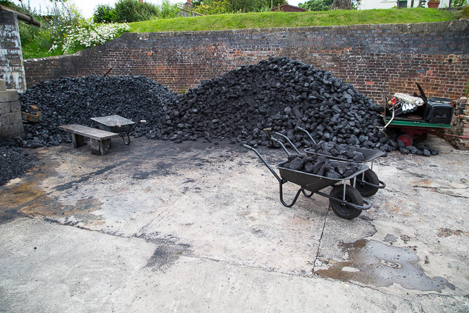
During the week ending 29 August 1846, the station was operated for 160 hours, and consumed 19 tons and 13 cwt of coal. This equates to 20 metric tonnes, or about 2.8 tonnes of coal per day. (1 cwt = one hundred weight = 112 pounds/lbs = 51 kg)
The later 1854 engine consumed about 30 cwt (1524 kg) of lower quality coal in a 24-hour day, and so was considerably cheaper to run.
Engine Staffing
Four staff were normally employed at Thames Head: a Carpenter, Carpenter's mate, a Fireman (for shovelling coal into the boilers) and the Engineman - the most senior.
When the engine was operating 24-hours a day, a relief Engineman would also have been employed.
The longest serving Engineman is thought to have been Thomas Toward. He was involved at the outset helping to install the first engine in 1792, and left the company some 42 years later.
Technical Details
1794 Engine
Design: Boulton & Watt
Stroke length: 8 ft (2.4 m)
Cylinder Diameter & Type: 50 inch (1.27 m) single acting
Beam Size: 24 ft x 43 inch x 39 inch made of Kelvedon Oak
Steam Pressure: 3 psi (pounds per square inch)(0.2 bar)
Strokes per minute: 10 (typical)
Boiler Type: Waggon (x2)
Pump diameter: 26 inch (660 mm)
Pump Type: Bucket
Gallons lifted per stroke: 162 (26 cu ft / or 736.5 litres)
Gallons lifted per hour: 65,000 (0.75 mega litres)
Gallons lifted per 24 hour day: 1,5 million (6.8 mega litres)
(Based on a quoted capacity of "about a lock-full per hour")
This engine was upgraded in 1833 when 2 new Waggon boilers were installed.
1854 Engine
Design: Boulton & Watt
Stroke length: 9 ft (2.75 m)
Cylinder Diameter: 40 inch (1.01 m) double acting
Beam size: unknown - made of cast or wrought iron
Beam weight: 10 tons
Steam Pressure: 20 psi (pounds per square inch) (1.38 bar)
Strokes per minute: 8 (typical)
Boiler Types:
1854: 1 x Waggon and 1 x Elliptical
1888: 1 x Lancashire
Pump diameter: 30 inch (762 mm)
Pump Type: Bucket
Gallons lifted per stroke: 300 (1364 litres)
Gallons lifted per hour: 144,999 (0.6 mega litres)
Gallons lifted per 24 hour day: 3 million (13.6 mega litres)
(Capacity calculated which concurs with the quoted figure of 3 million gallons per day)
Pump Well
Main dimensions: 10 ft x 15 ft oval-shaped shaft 63 ft 8 in deep.
The well shaft was lined with a 2 ft thick stone wall. The well also had a number of horizontal galleries off the main shaft, to allow more water in. The most important of these was the 'Little Tunnel' at a depth of 55 ft 8 in which it is believed connected into other wells nearby.
Lowest depth of water recorded in the well was 14.5 ft, measured from the bottom.
Future Canal Restoration
Any plans for the future restoration of this section of the Thames & Severn Canal will not include the reinstatement of a pumping station at Thames Head.
The reason for this is quite simple. It would not be possible to get a license to abstract significant quantities of water from this site, and certainly not up to 3 million gallons a day!
Acknowledgements & Further Information
Acknowledgements:
- Photo of Thames Head Wind Pump and Boulton & Watt Indenture courtesy of Gloucestershire Archives
- Photos of Thames Head Pumping Station reproduced by permission of Oxfordshire County Council
Sources and further information:
- The Thames & Severn Canal by Humphrey Household. Amberley Publishing
- Gloucestershire Archives
- Crofton Pumping Station near Marlborough, Wiltshire
- Crofton Beam Engines website (Kennet & Avon Canal)
- Archives Division of Birmingham Central Library
- British Newspaper Archive